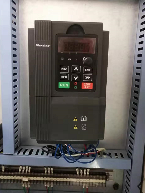
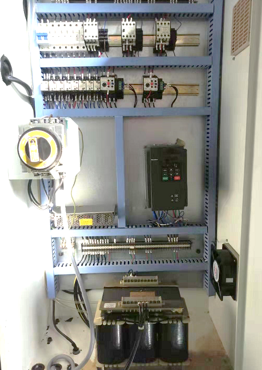
一、Application introduction
At present, the whole series of new vector control universal inverter of Meixin Electric has automatic measurement of asynchronous motor parameters, automatic identification, adaptive function, the general frequency converter with this function can automatically identify the parameters of the asynchronous motor before driving the asynchronous motor for normal operation, and adjust the relevant parameters in the control algorithm according to the identification results, so as to carry out effective vector control of the ordinary asynchronous motor.
System structure and operation mode of CNC lathe spindle frequency conversion
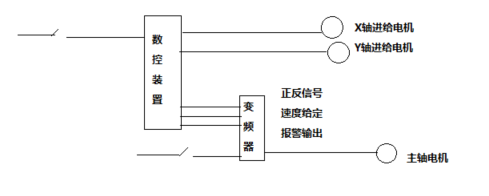
The basic principle of spindle frequency conversion control
From the asynchronous motor theory, the speed formula of the spindle motor is:
n=(60f/p)×(1-s)
where P - the number of pole pairs of the motor, s - slip rate, f - frequency of the power supply, n - the speed of the motor. It can be seen from the above formula that the motor speed is approximately proportional to the frequency, and the motor speed can be smoothly adjusted by changing the frequency, and for the inverter, the frequency adjustment range is very wide, and it can be adjusted arbitrarily between 0~600Hz (or even higher frequency), so the spindle motor speed can be adjusted within a wide range. Of course, after the speed is increased, the influence on its bearings and windings should also be considered to prevent excessive wear and overheating of the motor, which can generally be limited by setting the highest frequency.
二、Hardware wiring
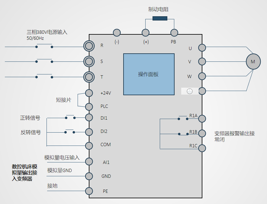
Note: The above is the schematic diagram of the inverter terminal block, and the definition of the terminal is subject to the actual product.
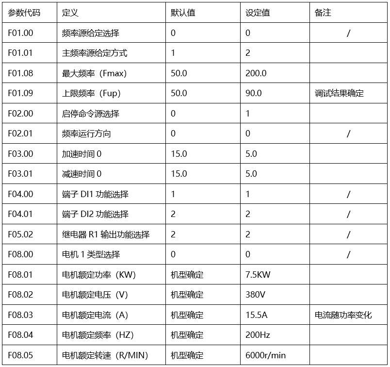
三、Parameter settings
The table shows the basic settings of the inverter parameters, and "/" is the default value. Refer to the manual for functional details; The F01.09 parameter is the value determined after debugging, please refer to the debugging test for details.
四、Debug tests
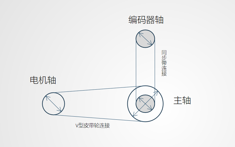
The motor shaft and the spindle are connected by V-pulleys. On the left is the motor shaft, and on the right is the spindle. The specific wheel size is subject to the actual situation on site. The spindle is connected to the external encoder via a timing belt. Upper encoder shaft, lower spindle. The modulus of the two synchronous wheels is the same.
五、Debugging process
1. Turn on the CNC machine tool system
2. Manually enter the starting spindle and the G code for the given speed
3. Run the program and observe the actual speed value of the given speed and the encoder feedback spindle
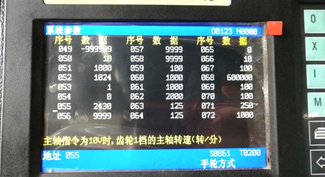
4. Adjust the system parameters so that the given speed value matches the actual speed value, and adjust the P055 parameters through the motor shaft pulley and the spindle pulley (for the Heiedman CNC system, the parameters of different CNC systems are different)
5. Limit the maximum number of revolutions of the spindle and adjust the parameter rate of the inverter F01.09
6. Spindle motor, voltage: Y380V, current: 15.5A, power: 7.5kw, revolution: 6000r/min, frequency: 200Hz
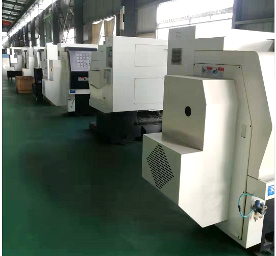
六、Device description MR200-4T-7.5B
